What Is a Parallel Circuit
Parallel Circuit is a type of electrical circuit in which components are connected across common points or junctions, forming multiple paths for the current to flow. Unlike a series circuit, where electricity flows through a single path, a parallel circuit allows current to split and flow through multiple branches simultaneously. This fundamental difference affects voltage, current distribution, and the overall behavior of the circuit.
In a each component receives the full voltage of the power source. For example, if a parallel circuit is connected to a 12-volt battery, each branch sees the full 12 volts regardless of how many components are connected. This is why are commonly used in households, where every appliance requires the same voltage to operate efficiently.
Understanding parallel circuits is essential for both beginners and advanced learners in electrical engineering, electronics, and physics. They are foundational for designing practical electrical systems, from home wiring to electronic devices, and are often the first concept students encounter when exploring electricity beyond simple series circuits.
How a Parallel Circuit Works

The working principle of a circuit revolves around Ohm’s Law and the concept of multiple current paths. In a parallel arrangement, the total current from the source splits among the branches based on each branch’s resistance. Branches with lower resistance draw more current, while higher resistance branches draw less. Mathematically, Parallel Circuit the total current is the sum of the currents in all individual branches.
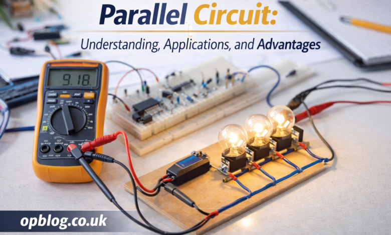
Voltage across each component in a parallel circuit remains the same. This is one of the defining characteristics and differentiates parallel from series circuits. For instance, if you connect three identical light bulbs in parallel to a battery, each bulb will glow at full brightness because each experiences the same voltage as the source.
Parallel circuits also feature a unique method of calculating total resistance. The reciprocal of the total resistance is equal to the sum of the reciprocals of each individual resistance. This property often confuses beginners, but it is essential for designing efficient circuits that meet specific current and voltage requirements.
Key Features of Parallel Circuits
One of the most important features of a parallel circuit is independence of components. If one branch fails or a component is removed, the other branches continue to operate normally. This reliability is a major reason why parallel circuits are preferred in home and industrial wiring.
Another defining feature is voltage uniformity. As mentioned, each component in a parallel circuit receives the same voltage as the source, ensuring consistent operation. This is crucial for appliances and devices that are sensitive to voltage changes, such as computers, refrigerators, or LED lights.
Additionally, allow flexible current distribution. Different branches can carry different amounts of current depending on their resistance. This flexibility enables engineers and designers to create complex systems where multiple devices or components can operate efficiently without overloading a single path.
Advantages of Parallel Circuits
Parallel offer several significant advantages over series circuits. First, they provide consistent voltage to all devices, making them ideal for household electrical systems. Without this consistency, appliances might receive insufficient voltage, leading to poor performance or damage.
Second, reliability is enhanced in parallel circuits. If one device fails or a branch is disconnected, the remaining branches continue to function. This redundancy is especially important in critical systems like hospitals, industrial machinery, or emergency lighting, where uninterrupted operation is vital.
Third, allow for flexible expansion. New devices or components can be added without affecting existing components. This ease of modification makes parallel circuits highly practical in real-world applications, where electrical systems often need upgrades or expansions over time.
Disadvantages and Considerations
Despite their advantages, parallel circuits also have some limitations. One of the main challenges is higher complexity in design and installation compared to series circuits. Multiple branches and junctions require careful planning to ensure proper current distribution and safety.
Another consideration is increased current draw. Since each branch draws current independently, the total current from the source increases with additional branches. This requires the power source and wiring to handle higher currents safely, which can increase costs and the risk of overheating if not managed properly.
Additionally, fault detection can be more challenging in complex. While a single component failure doesn’t stop the entire system, finding the faulty branch may require detailed inspection, especially in circuits with many branches or intricate wiring.
Common Applications of Parallel Circuit
Parallel circuit are used extensively in daily life and industrial applications. In homes, they form the backbone of electrical wiring. Lights, outlets, and appliances are typically connected in parallel to ensure they receive the same voltage and operate independently of one another.
In electronics, are crucial for powering devices that require consistent voltage. Circuit boards often use parallel arrangements to ensure multiple components operate correctly without affecting each other. Batteries are also connected in parallel to increase total current while maintaining voltage stability.
Industrial applications include large-scale machinery, factory lighting, and emergency systems. Parallel circuits provide redundancy and flexibility, ensuring that critical equipment remains operational even if one component fails. This reliability is a key reason dominate practical electrical and electronic system designs.
How to Calculate Parallel Circuit Parameters
Calculating parameters in a parallel circuit involves understanding Ohm’s Law and the rules for combining resistances and currents. The total resistance RtotalR_{total}Rtotal is found using the formula:
1Rtotal=1R1+1R2+1R3+…\frac{1}{R_{total}} = \frac{1}{R_1} + \frac{1}{R_2} + \frac{1}{R_3} + …Rtotal1=R11+R21+R31+…
The total current ItotalI_{total}Itotal drawn from the source is the sum of currents in each branch:
Itotal=I1+I2+I3+…I_{total} = I_1 + I_2 + I_3 + …Itotal=I1+I2+I3+…
Voltage across each branch remains equal to the source voltage:
Vbranch=VsourceV_{branch} = V_{source}Vbranch=Vsource
Using these formulas, engineers and students can design circuits to ensure proper current distribution, component operation, and safety. Proper calculation is essential to avoid overloading, overheating, or inefficient operation.
Final Thoughts on Parallel Circuits
Parallel circuits are a cornerstone of electrical engineering, offering reliability, voltage consistency, and flexibility in design. From household wiring to complex electronics and industrial machinery, parallel circuits make modern life possible. Their independence of components and uniform voltage delivery make them preferable for systems where safety and performance are critical.
Understanding parallel circuits is essential for students, hobbyists, and professionals. It provides a foundation for exploring more advanced electrical concepts, designing efficient systems, and troubleshooting real-world problems. With proper knowledge, anyone can appreciate how this fundamental circuit type powers the devices and infrastructure we rely on every day.